Mesh Generation
At this point, the DEM should be sufficiently post-processed, and we can begin the process of constructing a TIN.
TIN generation is done in several discrete steps:
- Triplane (surface) generation
- Applying elevation to surface
- Extruding into defined layers
- Applying materials to layers
Steps 1+2 and steps 3+4 are controlled with the following methods, respectively:
DEM.build_refined_triplane(**kwargs) # Steps 1 & 2
DEM.build_layered_mesh(**kwargs)     # Steps 3 & 4
Details on using these methods will be explained in the subsections below; for more information, read the method documentation.
Building a Surface Mesh
By default, TINerator will automatically determine whether to contruct a surface
with refined or uniform triangles. If watershed delineation has not been performed,
or the class variable DEM.feature = None, then TINerator will
generate a uniform surface. Otherwise, it will be refined.
The generated surface mesh will maintain the same spatial domain as the parent DEM. This may cause overflow errors if the DEM domain is close to or exceeds the limit of a double-precision float.
Uniform
Once the boundary is generated, calculating a triplane is as simple as:
my_dem.build_uniform_triplane(edge_length)

By default, DEM elevation data will be continuously interpolated onto the
Z-values of the surface triangles. A completely flat mesh can be constructed
instead with the method argument apply_elevation = False.
Refined
For generating a refined surface, call the method:
my_dem.build_refined_triplane(min_edge,max_edge)
where min_edge will be the shortest edge generated in the refining process, and max_edge will be the longest.
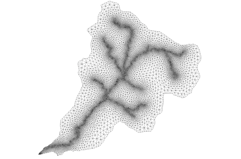
This method works by (i) coarsely triangulating the interior of the boundary, and (ii) adaptively refining triangles according to a gradient field.
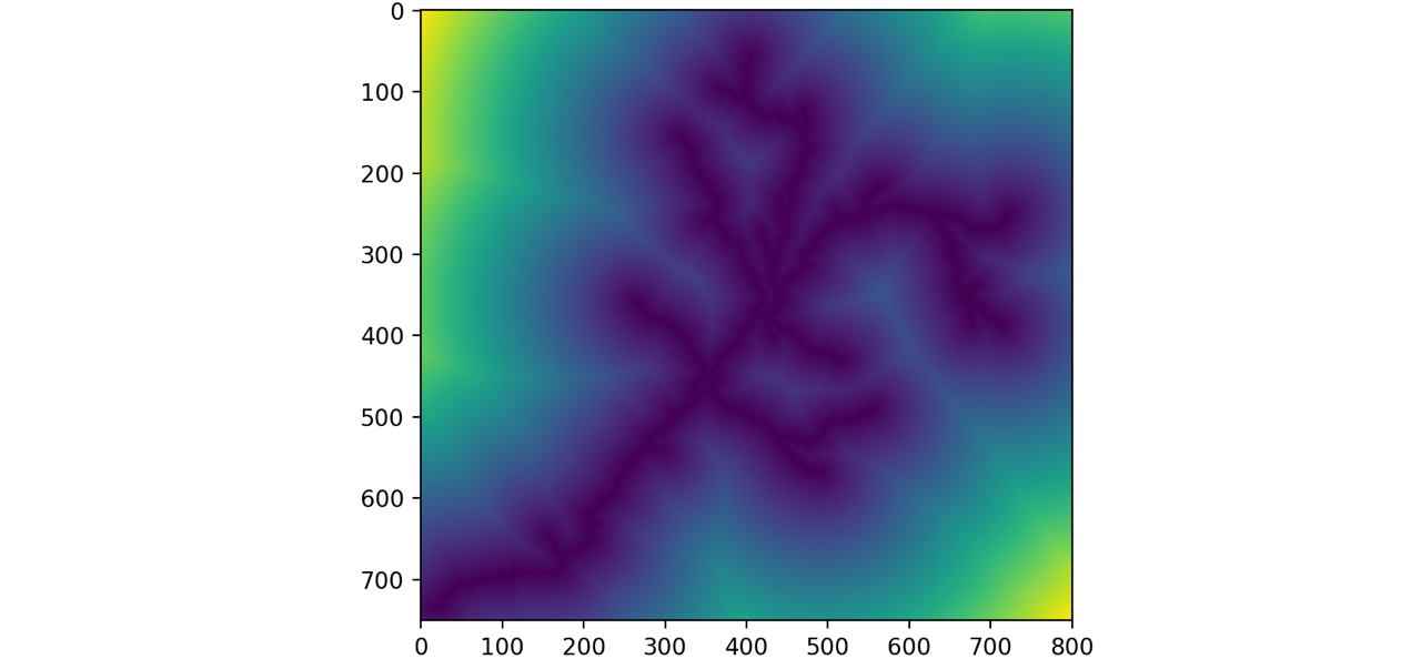
The gradient field is a raster with values that scale relative to the Euclidean distance from the feature.

Triangle edge length scales linearly from min_edge, where the gradient field is
0 (at the feature), towards max_edge, where the gradient field is 1 (at the
edge of the DEM domain), according to this equation:

As stated above, DEM elevation data will be interpolated onto the Z-coordinate of the surface nodes unless explicitly defined otherwise.
Mesh Quality
Triangulation is done with a Delaunay triangulation algorithm, and
the mesh is iteratively smoothed with Laplacian smoothing.
The number of smoothing / reconnection iterations can be controlled with the keyword iterations:int.
Mesh quality can be found through the method:
DEM.quality('surface')
This returns a dictionary containing aspect ratio statistics (\theta_{max} / \theta_{min}), edge length ratio statistics (e_{max} / e_{min}), and count of malformed elements (triangles with very large angles, very small angles, or very small areas).
Stacking the Mesh
Mesh extrusion is the process of extruding a triangular surface mesh into a volumetric prism mesh. This method is called using
tinerator.DEM.layeredMesh(**kwargs)
For more information, see the documentation.
As an example, after generating a triangular surface mesh, it can be layered by:
layers = [0.1, 0.3, 0.6, 8., 21.] # Define layer thickness
matids = [  1,   2,   3,  4,   5] # Define material ID

my_dem.build_layered_mesh(layers,matids=matids)
where layers is a list of length N, containing the sequential depths of
layers to extrude, and matids is a list of length N containing the
sequential integer IDs for each layer.
For example, layer 1 will have a depth of 0.1 meters and a material ID of 1, layer 2 will have a depth of 0.3 and a material ID of 2, and so on.
Note
The length of list layers must equal the length of list matids
Layers
Depending on your particular use case, you may want as few as one layer, or many more. Layers may be of any arbitrary thickness, with units the same as the DEM parent.
Note that the number of elements in the volumetric mesh, N_{volume}, is directly proportional to the number of layers n_{layers}:
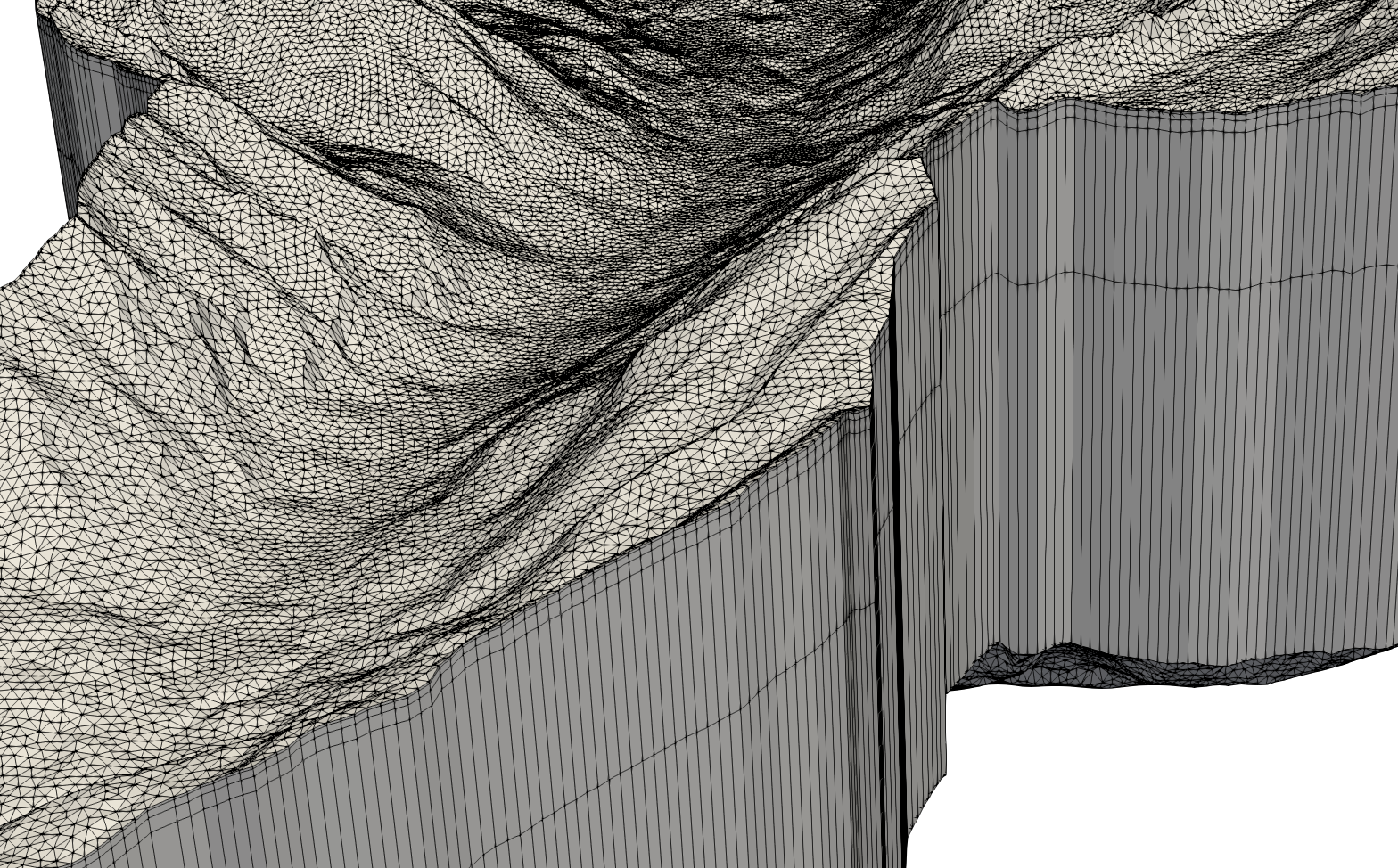
 Five-layer prism mesh. Layer depths have been strongly exaggerated for effect.
Materials
Each layer can optionally have its own material ID - this provides an easy way to identify which layer an element is in, or to find elements within a defined layer. Note that material ID is not necessarily an attribute - it is a non-zero integer value mapped to an element. Cell and node based attributes are applied using a different process - read more here.
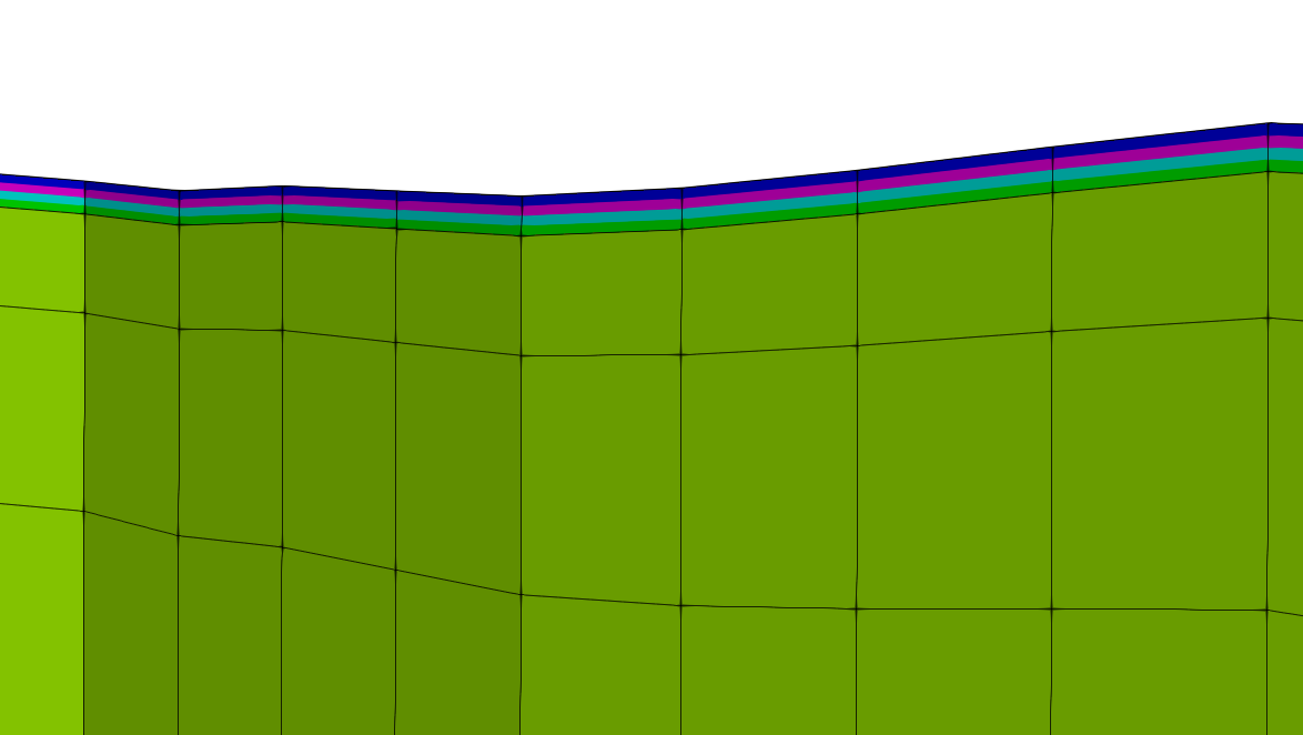
 An exaggerated view of layers colored by material ID. Note that some values are
unique to its layer, while other layers share an ID.