Of the laboratories reporting real totals for soils in Wageningen inter-laboratory proficiency testing programs, about 40% report XRF concentrations in pressed powders, while about 10% report XRF concentrations in fused samples.
Using XRF spectroscopy, it is possible to quantify a wide range of elements in soil/sediment, including those listed in Table 17.3. The technology is dependent on expensive instrumentation, including an X-Ray tube that is a potential radiation hazard. Accordingly, the instrument must be operated with full attention to safety, while operators must wear and monitor a personal X-Ray monitor at all times.
A polychromatic beam of primary X-Rays is used to excite an XRF spectrum comprising fluorescent light, the wavelengths of which are characteristic of elements in the soil/sediment. Certified and secondary reference soils can be used to calibrate the XRF spectrometer.
This method, which extends Method 17A1 (total soil K) from Rayment and Higginson (1992), is based on the techniques described by Norrish and Hutton (1964), LaChance and Traill (1966) and Rousseau (1984). The calibration approach and analytical techniques are similar to those described earlier for total P and total S. Soils need to be dry, finely ground (<0.05 mm) and pelleted prior to measurement.
To minimise the likelihood of the dry-powder pellets cracking and exploding under vacuum (this is quite common for very sandy soils), boric acid (H3BO3) is routinely incorporated as a binding material prior to pelleting at high pressure. Examples of typical measurement-performance characteristics for Method 17A1 are shown in Table 17.3.
Table 17.3. Typical uncertainty, lower limits of reporting (LOR) and calibration ranges for Method 17A1.
Analyte |
Uncertainty (%)# |
LOR |
Typical calibration range |
Al |
5 |
0.5% |
0–10.0% |
As |
15 |
40 mg/kg |
0–500 mg/kg |
Ca |
5 |
0.01% |
0–4.0% |
Co |
8 |
10 mg/kg |
0–30 mg/kg |
Cr |
5 |
15 mg/kg |
0–350 mg/kg |
Cu |
8 |
10 mg/kg |
0–200 mg/kg |
Fe |
5 |
0.4% |
0–8.0% |
K |
5 |
0.025% |
0–2% |
Mg |
5 |
0.04% |
0–1.2% |
Mn |
5 |
28 mg/kg |
0–1600 mg/kg |
Ni |
5 |
10 mg/kg |
0–120 mg/kg |
Pb |
15 |
40 mg/kg |
0–750 mg/kg |
Si |
5 |
1.2% |
0–45% |
Sr |
10 |
15 mg/kg |
0–200 mg/kg |
Ti |
5 |
0.05% |
0–2.0% |
V |
5 |
10 mg/kg |
0–150 mg/kg |
Zn |
8 |
30 mg/kg |
0–1200 mg/kg |
#Uncertainty estimates are based on two times relative standard deviations of replicated analysis of reference materials over time (D Lyons, pers. comm.).
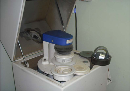
Figure 17.1. A ring and pluck head used for soil grinding in a ‘shatterbox’.
Zirconia Ring and Puck Head and Compatible ‘Shatterbox’ Mill.
100 g capacity zirconia ring and puck head: see Figure 17.1.
X-ray Fluorescence Spectrometer
An XRF instrument capable of operating over the desired wavelength range as required for the analytical suite: see Figure 17.3.
70 Kilo-newton Press
A press capable of preparing pellets compressed to 70 kilo-newtons is used to press the soil samples into Al cups.
Silica Sand
This may be purchased then acid washed. Alternatively, prepare as described by Hewitt (1966).
Preparation of Pellets
Taking precautions (e.g. see Zief and Mitchell 1976) to avoid/eliminate contamination from the elements of interest, oven-dry (65°C) ≈20–30 g air-dry soil (<2 mm), then weigh 10.00 g of soil and 0.5 g of H3BO3 into the same numbered polystyrene or other suitable container and mix well. The H3BO3 is added to serve as a binder. Re-dry the mix in a forced-draught oven at 65°C for 12–24 h. Place each mix separately into a clean 100 g capacity ring and pluck head and grind in a ‘shatterbox’ for a minimum of 3–5 min, or until soil particle size is <0.05 mm. This is generally sufficient time to eliminate the effects of particle size and non-homogeneity (see Note 1).
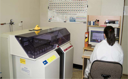
Figure 17.2 A modern XRF instrument with an automatic sample changer loaded with dry-powder soil pellets.
Next pellet about 2–5 g soil/H3BO3 mix (<0.05 mm) into a 45 mm diameter Al disc, using a hydraulic press of ≈70 kilo-newtons total force. Refer to manufacturer’s instructions for suitability of Al disks (cups) for the XRF sample changer. Label each pellet on its underside with sample identification details. Load pressed samples into the sample changer of the XRF Spectrometer.
Analysis
Follow manufacturer’s recommendations when using the XRF Spectrometer. As an example, for an Applied Research Laboratory 9400 sequential XRF Spectrometer, use the following settings:
• Tube – 3.6 kW rhodium anode XRF tube.
• Power – 50 kV at 50 mA to provide a compromise between the excitation of heavy and light elements, providing adequate sensitivities for the determination of both.
• Detection – flow proportional counters are used for the determination of Ca, Co, Cr, Cu, Fe, K, Mg, Mn, Ni, Si, Ti, V and Zn; a scintillation counter is used for the determination of As, Pb and Sr.
• Crystals – select on the basis of best sensitivity.
• Counting times – peak 30 sec, background 10 sec.
Calibrate the XRF Spectrometer using a combination of secondary reference materials (e.g. Wageningen reference soils or similar), certified reference materials (if available), or artificial standards prepared in a similar way to those for total P (Method 9A1). If using secondary reference materials or certified reference materials, prepare pellets as per the samples; i.e. drying and ring-mill grinding with H3BO3 binder.
After appropriate background corrections have been performed, plot the corrected intensities against concentrations (certified or median) for each analyte of interest. Suitability of calibration and an estimate of LOR can be assessed from regression and goodness-of-fit parameters.
Run drift standards to assess calibration drift and determine the need to re-normalise the calibration. Monitor accuracy of secondary and in-house check soils by control charting results.
Report elemental concentrations (% or mg/kg of element) on an oven-dry basis, which can be assumed without further calculation, if samples were oven dried at 65°C.
1. Soil sample residues in the grinding head of the ‘shatterbox’ can be a serious source of contamination, especially when components become worn. For routine applications, these residues can be overcome between samples by scrubbing and washing with water then drying. Alternatively, the residues can be minimised by grinding a small quantity of acid-washed silica sand between each unknown sample.
Figure 17.1. A ring and pluck head used for soil grinding in a ‘shatterbox’.