Redox potential is an electrical measurement that indicates the oxidation-reduction status of natural and custom-made soils. It is expressed numerically as Eh, with units of mV. Soil Eh is a valuable but difficult-to-measure attribute that helps when assessing soil health and genesis, in addition to providing guidance on soil fertility and the status of soil contaminants (Liu and Yu 1984). Eh reflects the tendency of a soil solution to transfer electrons to or from a reference electrode; i.e. it is a measure of electron pressure/availability in the soil solution (Vorenhout et al. 2004). From this, an estimate of whether the soil (particularly sub-soil) is aerobic, anaerobic, or a mix of the two is obtained. These conditions influence whether chemical compounds such as Fe and Mn are chemically reduced or mostly present in their oxidised forms (Vepraskas and Faulkner 2001; Table 3.3).
Soil redox values are dependent on measurement conditions and other soil properties. Slow electrode response in poorly poised (redox capacity) soils (e.g. Ponnamperuma 1972; Fiedler et al. 2007) is a further challenge. Usually, measurements are made in the field. Here, apparent redox potentials are influenced by drainage, the presence of reactive chemicals, and/or exposure of the soil to atmospheric interactions. Measures of both oxidation and reduction are required in Soil Taxonomy (Soil Survey Staff 1999) for ‘aquic’ conditions, although the duration of reduction is unspecified. Hydric soils are able to support the growth and regeneration of hydrophytic vegetation.
Redox reactions involve the transfer of electrons from reductors (e– donors or reducing agents) to oxidants (e– acceptors or oxidising agents). James and Bartlett (2000) provide many examples.
The capacity factor in redox is referred to as poise (pe) and is defined as the change in added equivalents of reductant or oxidant to bring about a one unit change in pe (or an Eh change of 59 mV). The concept is similar to that of buffer capacity for pH (Stumm and Morgan 1996).
The field method described for quantifying electron activity detects the potential difference between a Pt indicator electrode and a Ag/AgCl reference electrode, both connected to a millivoltmeter (e.g. Jackson 1956; James and Bartlett 2000; Vorenhout et al. 2004). The method assumes the Pt electrode is inert and does not react chemically, while achieving equilibrium with the electro-active species in the soil. Diurnal fluctuations are common and changes in Eh with soil depth are the norm.
Table 3.3. Examples of approximate Eh values for soÕs of different oxidatŠn status and at points of transitŠn for important redox pairs at pH 7.0.
Example |
|
≈Eh (mV) |
|
Soil status† |
|
|
|
Very well oxidised soil |
|
800 |
|
Well oxidised soil |
|
500 |
|
Moderately well oxidised soil |
|
300 |
|
Poorly oxidised soil |
|
100 |
|
Much reduced soil |
|
–200 |
|
Extremely reduced soil |
|
–500 |
|
Element†† |
Oxidised form |
Reduced form |
|
Oxygen |
O2 |
H2O |
+600 to +400 |
Nitrogen |
NO3– |
N2O, N2, NH4+ |
250 |
Manganese |
Mn4+ |
Mn2+ |
225 |
Iron |
Fe3+ |
Fe2+ |
+100 to –100 |
Sulfur |
SO42– |
S2– |
–100 to –200 |
Carbon |
CO2 |
CH4 |
<–200 |
† From Table 14.1 of Jackson (1956)
†† From Table 1 of Vorenhout et al. (2004)
Deionised Water
The water is to have an electrical conductivity of <10-4 dS/m, and have a CO2 concentration no more than that in equilibrium with the atmosphere. See Method 3A1 for more details.
≈ 4 M Hydrochloric Acid (HCl)
Prepare by adding ≈195 mL concentrated (ρ = 1.16 g/cm3; 31.5–33%w/v) HCl to about 200 mL deionised water slowly and with stirring. Cool, then dilute to 500mL.
1 M Hydrochloric Acid (HCl)
Aqua Regia
To 3 volumes of HCl slowly add 1 volume of HNO3 with stirring. Store the mixture in a safe location.
Electrode Platinizing Solution
Dissolve separately 1.0 mg platinic chloride [Cl6H2Pt.6H2O; also called chloroplatinic acid hexahydrate] in deionised water and 7.0 mg of lead(II) acetate [Pb(CH3COO)2] in deionised water, combine, mix well and make to 30 mL. This solution suffices for up to 100 electrodes each consisting of a 1–2 cm length of Pt wire.
≈ 0.05 M Potassium Hydrogen Phthalate pH 4.0 Buffer
Prepare an ≈0.05 M solution (actually 0.0496 M) by dissolving 10.12 g potassium hydrogen phthalate (KHC8H4O4; previously dried for 2 h at 110°C) and make to 1.0 L with water described for use with buffer solutions (Alvarez 1984). Exclusion of CO2 is unnecessary, but protect against evaporation and contamination. Store for up to one month but replace solution if mould appears.
3 M Potassium Chloride
Dissolve 223.7 g potassium chloride (KCl) and make to 1.0 L with deionised water.
Ferrous-Ferric Solution (Light’s Solution, for redox measurements and testing of electrodes)
This aqueous buffer solution of known and stable redox potential (+476 ± 20 mV with an Ag/AgCl reference electrode) was described by Light (1972). Prepare by dissolving/diluting each of the following three reagents in deionised water. Combine, mix thoroughly and dilute to 1.0 L in a volumetric flask. The three analytical grade reagents and weights/volumes of each are as follows:
1 0.100 M Ferrous ammonium sulfate [Fe (NH4)2 (SO4)2.6H2O]: 39.21 g/L
2 0.100 M Ferric ammonium sulfate [Fe (NH)4 (SO4)2.12H2O]: 48.22 g/L
3 1.0 M Sulfuric Acid [18 M H2SO4]: 56.2 mL/L (cool before combining with the other two reagent solutions).
Millivolt–pH–Eh Meter
Ideally, the meter should be portable, sensitive and reliable, able to operate reliably across the range +800 to –600 mV or wider.
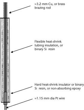
Figure 3.1. An example of one type of fabricated Pt-electrode for redox measurements. A Pt-wire length of 10–15 mm is ideal.
Platinum blackened platinum electrode/s
Purchase commercially or manufacture (see Figure 3.1) by sealing a short length of clean Pt wire in a glass tube, aided by means of lead glass melted around the Pt wire (or an equally effective, inert bonding agent). Further up, the Pt wire should be spot-welded (connected) to a Cu wire for subsequent connection to the positive terminal of a portable millivolt–pH–Eh meter. Alternatively, manufacture by brazing ≈1.15 mm Pt wire (with an appropriate flux) onto one end of 3.2 mm brass brazing rod, and crimping or brazing a suitable length of an ≈1.15 mm, multi-stranded Cu wire into a 3 × 1 mm slot cut into the opposite end of the brazing rod (length of rod as desired). Use rigid, heat-shrink tubing (or a suitable epoxy) to protect the brass rod from the environment. See Vepraskas and Cox (2002) for more details on Pt-electrode fabrication.
To blacken the Pt-electrode (or to refurbish previously used Pt electrodes), follow a two-part process of (a) pre-cleaning, and (b) ‘blackening’ Pt electrodes.
(a) Pre-cleaning
(b) ‘Blackening’ Pt electrodes (optional; see Note 1)
Reference Electrode
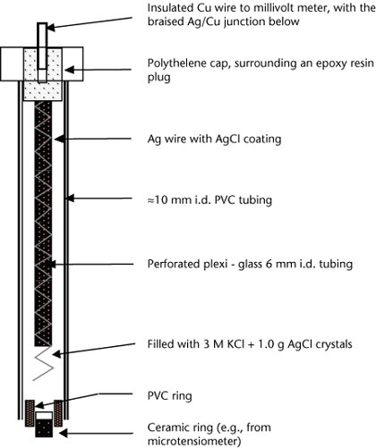
Either an Ag/AgCl or a Hg-based calomel reference electrode can be used, but Ag/AgCl reference electrodes are preferred (Figure 3.2; see Note 2). In the AgCl reference electrode, the Ag and Ag+ are surrounded by a solution of KCl, which maintains electrical neutrality. When the reaction goes to the right, K+ is released to the soil through the ceramic tip of the electrode. When the reaction is reversed, Cl– ions are released through the ceramic tip to the soil solution.
Fabricate or select a commercial Ag/AgCl reference electrode (or equivalent) able to deliver a defined and constant virtual grounding potential, stable against changes in outer electrolyte composition. The inner plexi-glass tube should contain ≈3–4 M KCl, saturated with AgCl. The lower tip, which must make full contact with the soil solution, should be of porous frit (e.g. porous ceramic material) permitting the slow passage of electrolyte to the soil. The Ag wire within the reference electrode must be coated with AgCl2. This coated wire (in the electrolyte solution) must be coupled to a low-noise cable (via the common terminal) to a millivolt–pH–Eh meter, to which the Pt electrode is also attached (voltage terminal). To ensure good/lengthy galvanic contact, reference electrodes with diaphragms of porous ceramic frit ≈70 times larger in diameter than conventional reference cells are recommended (Fiedler et al. 2007). Electrodes with polyvinyl chloride (PVC) shafts are desirable, with the ceramic diaphragm sealed within via waterproof resin.
Figure 3.2. An example of one type of fabricated Ag/AgCl reference electrode for redox measurements.
Connect (with solder) the Ag wire to a Cu wire for subsequent connection to battery or millivolt–pH–Eh meter. Internally, the Ag/Cu junction should be suspended in a perforated plexiglass tube (e.g. 6 mm i.d.) [filled with 3 M KCl + 1.0 g AgCl crystals/L (saturation) to prevent dissolution of the AgCl wire] all sealed inside the PVC electrode shaft. The electrode potential for the reference cell described is 204.6 mV, relative to the standard H2 electrode at 25°C, noting that the electrical potential is sensitive to sunlight.
Prior to use, clean the Ag wire (99.9% Ag; 0.5 mm) with ethanol, then immerse the Ag-wire (anode) and a Pt-wire (cathode) in 1 M HCl and apply a potential of 1.7 V to commence electrolysis, and continue for ≈5 min. A grey-brown coating of AgCl on the Ag wire should form and remain after removal and washing with running deionised water, followed by overnight standing in deionised water. See Fiedler et al. (2007) and Vepraskas and Cox (2002) for more details on reference electrode construction and preparation for use.
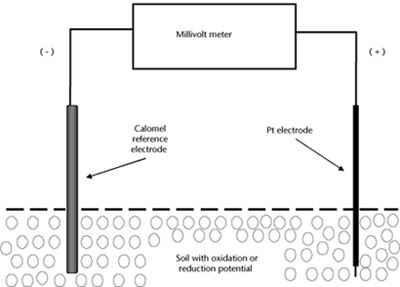
Figure 3.3. In-field configuration of electrodes and millvolt meter for Eh.
Install individual, pre-tested reference and Pt electrode arrays as shown in Figure 3.3 at predetermined depths or in particular soil horizons (see Note 3). Ensure the Pt electrode is intimately sealed into the fabric of the soil at the specified depth/s, using an aqueous slurry of soil obtained from the same site and depth. Air/O2 should not be trapped at either the soil-Pt-electrode interface or the soil-reference electrode interface, as this will result in the recording of high redox potentials. In contrast, electrodes placed in close proximity to atypical pieces of OM and sugars that are being oxidised by bacteria will be in reduced soil and will result in the recording of low redox potentials.
Install multiple electrode arrays to cover the Eh variations within soil horizons (typically 5–10 electrodes at each depth or zone of interest, to account for soil variability and the occasional failure of electrodes). Concurrently, record soil pH values and soil temperatures at similar, nearby locations. If voltage ‘drifting’ occurs, check whether human error or natural events might be the cause and respond accordingly (see Note 4). Operators have the option of using the Pt electrode with or without a platinized coating, with the former preferred.
When precise rather than relative redox measurements are required, redox field measurements need to be corrected to equate to the potential of a standard H+ electrode, which cannot be used in the field. This requires temperature and reference-electrode correction to the experimental millivolt readings. Use the examples given in Table 3.4 to account for minor effects of temperature on standard half-cell potentials of Ag/AgCl reference electrodes, as influenced by internal KCl concentrations. Separately determine experimentally the effects of soil pH on locally measured Eh values or work on the generic assumption that the pH factor is –59 mV/pH unit at 25°C (see Note 5).
Table 3.4. Effects of temperature on standard half-cell potentials (mV) of typical Ag/AgCl reference electrodes† with varying internal KCl concentratŠns (data of Fiedler et al. 2007).
Temperature (°C) |
3 M KCl |
3.5 M KCl |
4 M KCl |
10 |
220 |
215 |
214 |
20 |
213 |
208 |
204 |
30 |
205 |
201 |
194 |
40 |
198 |
193 |
184 |
† It is usually sufficient to use a correctŠn factor of +200 mV. For a calomel reference electrode, the corresponding standard half-cell correctŠn factor is ≈+250 mV.
Redox Potential (mV) = [Field Voltage (mV) + Correction Factor/s (mV)]
Report field Eh values (mV), retaining information on point-to-point variability.